DrawPrimitive |
One of the most important functions in DirectX 9 is DrawPrimitive. It can be used to draw different objects. DrawPrimitive takes three parameters. The first parameter indicates the type of primitive and can be any of:
Una de las funciones más importantes funciones en DirectX 9 es DrawPrimite. Esta puede ser usada para dibujar diferentes objetos. DrawPrimite toma tres parámetros. El primer parámetro indica el tipo de primitiva y puede ser cualquier de los siguientes valores:
|
device->IASetPrimitiveTopology |
One of the most important functions in DirectX 10 and 11 is IASetPrimitiveTopology. It can be used to draw different type of objects. The only parameter indicates the type of primitive and can be any of:
Una de las funciones mas importantes en DirectX 10 y 11 es IASetPrimitiveTopology. Esta puede ser usada para dibujar distintos tipos de objetos. El único parámetro indica el tipo de primitiva y puede ser: (ver la lista en inglés). |
Triangle List |
| A triangle list is a list of isolated triangles as shown in the figure below. They are use to create an object that is composed of disjoint pieces. DirectX allows applying a material and texture to a triangle list to simulate real scenes. A triangle list must have at least three vertices and the total number of vertices must be divisible by three. Una lista de triángulos es una lista de triángulos aislados como se muestra en la figura de abajo. Estas son usadas para crear un objeto que está compuesto de piezas separadas. DirectX permite aplicar un material y una textura a la lista de triángulos para simular escenas reales. Una lista de triángulos debe tener al menos tres vértices y el número total de vértices debe ser divisible entre tres. |
Triangle Strip |
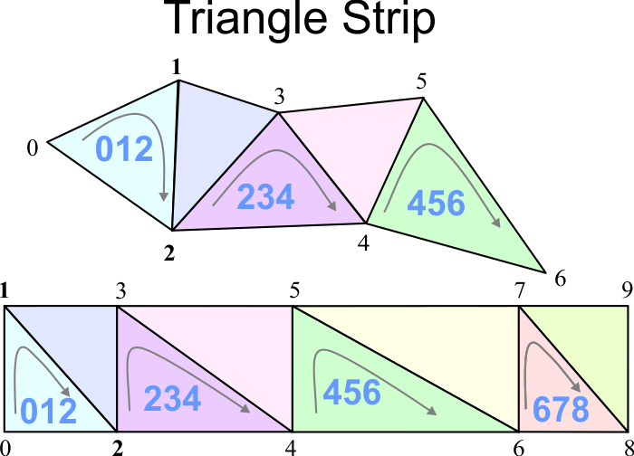
| A triangle strip is a list of connected triangles. As the triangles are connected, it is not necessary to repeatedly specify all three vertices of each triangle. In the figure below, only seven vertices are required to define (and draw) the triangle strip composed of five triangles: 012, 123, 234, 345, and 456. Triangle strips are used to define most objects in 3D scenes, including very complex objects such as people, cars, etc. Una banda de triángulos es una lista de triángulos conectados. Como los triángulos están conectados, no es necesario especificar en forma repetida los tres vértices de cada triángulo. En la figura de abajo, sólo se requieren siete vértices para definir (y dibujar) la banda de triángulos compuesta de cinco triángulos: 012, 123, 234, 345 y 456. Las bandas de triángulos son usadas para definir la mayoría de los objetos en escenas de 3D, incluyendo objetos muy complejos tales como personas, carros, etc. |
Degenerate Triangle |
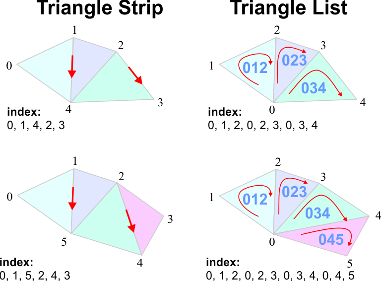
| A degenerate triangle is a triangle whose area is zero. A degenerate triangle can be included in a triangle strip to render triangles that are not connected to one another in DirectX 9. The code shown below draws two separate triangles. In DirectX 10 and 11, a strip-cut index is used to cut a strip, a strip-cut index is simply the maximum possible value for the index (0xffff for a 16-bit index, 0xffffffff for a 32-bit index) as shown in the figure. Un triángulo degenerado es un triángulo que tiene una área de cero. Un triángulo degenerado puede ser usado en una banda de triángulos para dibujar triángulos que no están conectados uno con el otro en DirectX 9. El código de abajo dibuja dos triángulos separados. En DirectX 10 y 11, un índice de corte de banda es usado para cortar una banda de triángulos, un índice de corte de banda es simplemente el máximo valor posible para el índice (0xffff para un índice de 16 bits, 0xffffffff para un índice de 32 bits) cómo se muestra en al figura. |
| Program.cpp |
| //_______________________________________ DirectX 9 CUSTOMVERTEX vertices[] = { {-5.0, -5.0, 0.0}, { 0.0, 5.0, 0.0}, { 5.0, -5.0, 0.0}, { 5.0, -5.0, 0.0}, // degenerate triangle {10.0, 5.0, 0.0}, // degenerate triangle {10.0, 5.0, 0.0}, {15.0, -5.0, 0.0}, {20.0, 5.0, 0.0} }; |
Indexes |
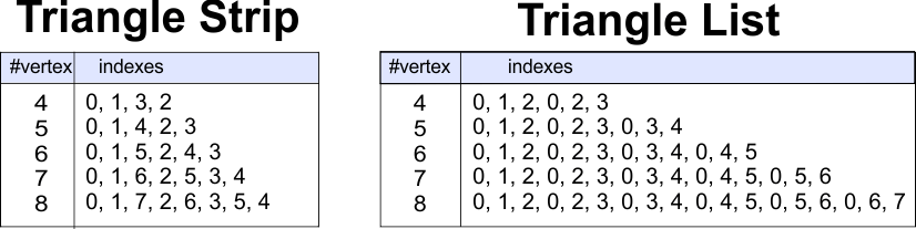
| The table below shows the indexes of a polygon using a Triangle Strip and a Triangle List. La tabla de abajo muestra los índices de un polígono usando un Triangle Strip y una Triangle List. |
Triangle Fan |
| Triangle Fans are not longer supported in new versions of DirectX because Triangle Strips can do anything that Triangle Fans can do. A triangle fan can be used to draw a polygon or a circle. Los Ventiladores de Triángulos ya no son soportados en las nuevas versiones de DirectX porque las Bandas de Triángulos pueden hacer todo lo que los Ventiladores de Triángulos pueden hacer. Un ventilador de triángulos puede usarse para dibujar un polígono o un círculo. |
Vertex Buffer in DirectX 9 |
| When drawing a set of vertices, performance can be improved using vertex buffer. In this case the vertex values are not filled with the vertices every time the screen is drawn, instead the buffer is created only once before the first rendered. A vertex buffer requires a smart pointer member variable as shown in the header file shown below. The source file shows how to use a vertex buffer. First, the vertex buffer is created. Second, the buffer memory must be locked. Third, vertices data is copied to the vertex buffer. Finally, the buffer memory must the unlocked as shown below. Cuando se dibujan un conjunto de vértices, el desempeño puede ser mejorado usando un buffer de vértices. En este caso los valores de los vértices no son llenados cada vez que se dibuja la pantalla, en su lugar el buffer es creado solamente una vez antes de dibujar la pantalla por primera vez. Un buffer de vértices requiere una variable miembro del tipo puntero inteligente como se muestra en el archivo de encabezado mostrado debajo. El código fuente mostrado debajo ilustra cómo usar un buffer de vértices. Primero, el buffer de vértices es creado. Segundo, se coloca un candado en la memoria del buffer. Tercero, los datos de los vértices son copiados al buffer. Finalmente, el candado de la memoria del buffer es removido como se muestra debajo. |
| Program.h |
| #pragma once //______________________________________ Program.h #include "Resource.h" class Program: public Win::Window { public: Program() { } ~Program() { } IDirect3DVertexBuffer9* vertexBuffer; ... }; |
| Program.cpp |
| void Program::Window_Open(Win::Event& e) { ... CG::Vertex vertex[] = { { -1.0f,-1.0f, 0.0f, 0xffff0000, }, { 1.0f,-1.0f, 0.0f, 0xff0000ff, }, { 0.0f, 1.0f, 0.0f, 0xff00ff00, }, }; try { //_______________________________________________________ 1. CREATE d3dDevice->CreateVertexBuffer(3*sizeof(Game::Vertex), 0, D3DFVF_XYZ|D3DFVF_DIFFUSE, D3DPOOL_DEFAULT, &vertexBuffer, NULL); VOID* pVertices; //_______________________________________________________ 2. LOCK vertexBuffer->Lock(0, sizeof( vertex ), ( void** )&pVertices, 0 ); //_______________________________________________________ 3. COPY memcpy( pVertices, vertex, sizeof(vertex) ); //_______________________________________________________ 4. UNLOCK vertexBuffer->Unlock(); } catch(_com_error & e) { this->MessageBox(e.ErrorMessage(), L"COM Error", MB_OK | MB_ICONERROR); } . . . } |
| Tip |
| The code shown below illustrates how to render a vertex buffer in DirectX 9. First, the SetStreamSource function is called to set a specific vertex buffer corresponding to an object in the scene. Second, the DrawPrimite function can be used to draw the object. El código de abajo ilustra como dibujar un buffer de vértices en DirectX 9. Primero, la función SetStreamSource es llamada para fijar un buffer de vértices específico que corresponde a un objeto en la escena. Segundo, la función DrawPrimitive puede ser usada para dibujar el objeto. |
| Program.cpp |
| bool Program::RenderScene() { ... d3dDevice->SetStreamSource( 0, vertexBuffer, 0, sizeof(CG::Vertex) ); d3dDevice->SetFVF(D3DFVF_XYZ|D3DFVF_DIFFUSE); d3dDevice->DrawPrimitive(D3DPT_TRIANGLELIST, 0, 1); ... } |
Normal Vector |
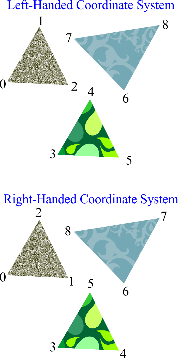
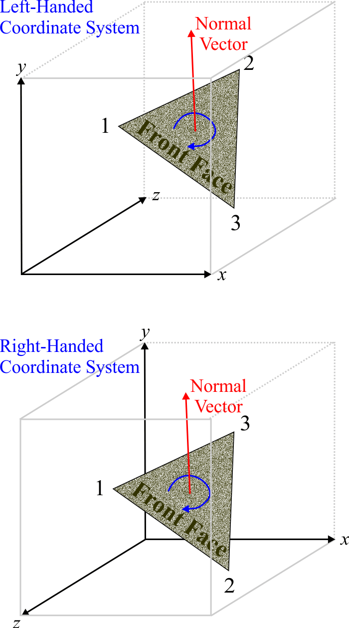
| A normal vector is a unit vector perpendicular to a surface. The direction of the vector is determined by the order in which the vertices are defined and the coordinate system. The surface has two faces: the back face and the front face as shown in the figure. DirectX does not always render back faces. Normal vectors can also be assigned to each vertex, in this case, the normal vector can be used to produce effects on the surface of the object such as lighting. Un vector normal es un vector perpendicular a una superficie. La dirección del vector está determinada por el orden en el cual los vértices están definidos y el sistema de coordenadas. La superficie tiene dos caras: la cara de atrás y la cara enfrente como se muestra en la figura. DirectX no siempre dibuja ambas caras. Los vectores normales pueden ser asignados a cada vértice, en este caso, el vector normal puede ser usado para producir efectos en la superficie del objecto tales como iluminación. |
Normal Vector Computation |
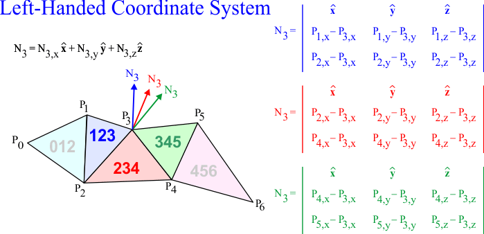
| It is possible to compute the normal vector for each vertex in a triangle using the cross product as shown in the figure. In a triangle strip, each vertex is shared by three triangles, and therefore, the resulting normal is usually computed as the average of the three normal vectors. In a more complex mesh, each vertex may be shared by more than three triangles, and consequently, the resulting normal may be computed as the average of all the normal vectors of the adjacent triangles. Es posible calcular el vector normal para vértice en un triángulo usando el producto cruz cómo se muestra en la figura. En una banda de triángulos, cada vértice está compartido por tres triángulos, y por lo tanto, la normal resultante es usualmente calculada cómo el promedio de los tres vectores normales. En un malla más compleja, cada vértice puede ser compartido por más de tres triángulos, y consecuentemente, la normal resultante puede ser calculada como el promedio de todas los vectores normales de los triángulos adyacentes. |
Culling in DirectX |
| DirectX has several options to draw the faces of the surface, these options are called culling options. You can use the SetRenderState function to set the culling mode in DirectX 9. The options are: D3DCULL_NONE (no culling), D3DCULL_CW (clockwise culling), and D3DCULL_CCW (counter clockwise culling). In DirectX 11, you can use the D3D11_RASTERIZER_DESC structure to set the CullMode, the available values are: D3D11_CULL_NONE, D3D11_CULL_BACK and D3D11_CULL_FRONT. DirectX tiene varias opciones para dibujar las caras de una superficie, estas opciones son llamadas opciones de culling. Usted puede usar la función SetRenderState para fijar el modo de culling en DirectX 9. Las opciones son: D3DCULL_NONE (no culling), D3DCULL_CW (culling en la dirección de las manecillas reloj), and D3DCULL_CCW (culling en la dirección contraria a las manecillas reloj). En DirectX 11, usted puede usar la estructura D3D10_RASTERIZER_DESC para fijar el CullMode, los valores disponibles son: D3D11_CULL_NONE, D3D11_CULL_BACK y D3D11_CULL_FRONT. |
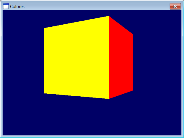
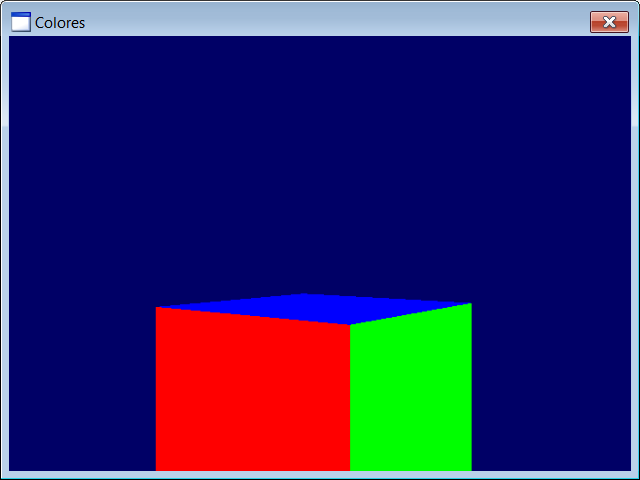
| Problem 1 |
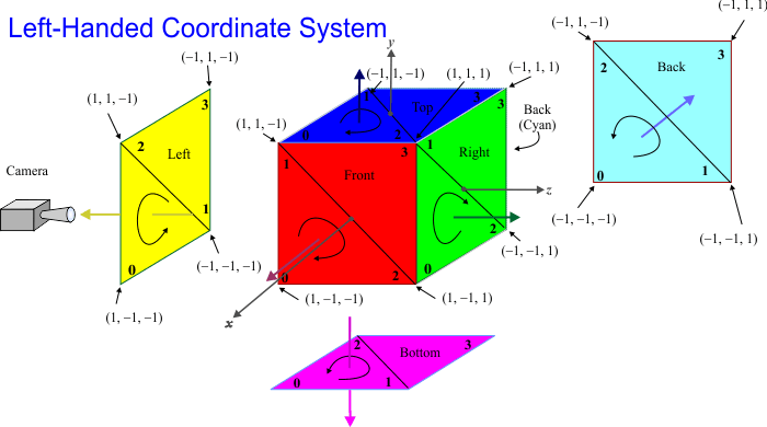
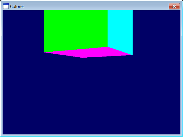
| Create a DirectX application called Colores to draw a cube using triangle strips. The cube must rotate horizontally. Use the following colors for the cube faces: red, blue, green, yellow, purple, and cyan. Be sure to set the appropriate culling mode. Each face requires four vertex. The full cube requires 24 vertex. The number of indexes is 24 plus five to separate each triangle strip with a strip-cut index, a total of 29 indexes. Use D3D11_PRIMITIVE_TOPOLOGY_TRIANGLESTRIP. Add a DirectX object called Cube and a DirectX scene called MainScene. Cree una aplicación de DirectX llamada Colores para dibujar un cubo usando bandas de triángulos. El cubo de rotar en forma horizontal. Use los siguientes colores para las caras del cubo: rojo, azul, verde, amarillo, morado y azul claro. Cada cara requiere cuatro vértices. El cubo completo requiere 24 vértices. El número de índices es 24 más cinco adicionales índices para separar cada banda de triángulos con un índice de corte de banda, un total de 29 índices. Use D3D11_PRIMITIVE_TOPOLOGY_TRIANGLESTRIP. Agregue un objeto de DirectX llamado Cube y una escena de DirectX llamada MainScene. |
| Cube.h |
| //____________________________________________________________ Cube.h #pragma once class Cube : public DX11::Object3D { float angleY = 0.0f; bool OnCreateScene(DX11::Engine& engine); . . . }; |
| Cube.cpp |
| . . . void Cube::OnUpdate(DX11::Engine& engine, float sec, float deltaSec) { angleY += (0.5f*deltaSec); world = DirectX::XMMatrixRotationY(angleY); if (angleY > DirectX::XM_2PI) angleY -= DirectX::XM_2PI; } void Cube::OnRender3D(DX11::Engine& engine) { engine.shaderColor.Render(engine, world, vertexBuffer->GetIndexCount(), 0, 0); } . . . |
| Colores.h |
| #pragma once //______________________________________ Colores.h #include "Resource.h" #include "MainScene.h" class Colores : public DX11::Window { public: MainScene mainScene; DX11::ColorVertexBuffer vb; }; |
| Colores.cpp |
| . . . int APIENTRY wWinMain(. . .) { Colores app; //_________________________________________________________________ 1. Vertex Setup const int indexCount = 29; const int vertexCount = 24; if (app.vb.CreateData(indexCount, vertexCount, D3D11_USAGE_DEFAULT, D3D_PRIMITIVE_TOPOLOGY_TRIANGLESTRIP) == false) { ::MessageBox(NULL, L"Unable to create vertex buffer", L"Colores", MB_OK | MB_ICONERROR); return 0; } unsigned int i; DX11::ColorVertex *vertex = app.vb.vertex; unsigned long *index = app.vb.index; //_________________________________ Blue Top for (i = 0; i < 4; i++) vertex[i].color = DirectX::XMFLOAT4(0.0f, 0.0f, 1.0f, 1.0f); vertex[0].position = DirectX::XMFLOAT3(1.0f, 1.0f, -1.0f); vertex[1].position = DirectX::XMFLOAT3(-1.0f, 1.0f, -1.0f); vertex[2].position = DirectX::XMFLOAT3(1.0f, 1.0f, 1.0f); vertex[3].position = DirectX::XMFLOAT3(-1.0f, 1.0f, 1.0f); //_________________________________ Yellow Left . . . //_________________________________ Red Front . . . //_________________________________ Green Right . . . //_________________________________ Cyan Back . . . //_________________________________ Magenta Bottom for (i = 20; i < 24; i++) vertex[i].color = DirectX::XMFLOAT4(1.0f, 0.0f, 1.0f, 1.0f); vertex[20].position = DirectX::XMFLOAT3(1.0f, -1.0f, -1.0f); . . . //____________________________________________________________________ 2. Index Setup index[0] = 0; // Top face index[1] = 1; index[2] = 2; index[3] = 3; index[4] = 0xffffffff; //strip-cut index index[5] = 4; // Left face index[6] = 5; index[7] = 6; index[8] = 7; index[9] = 0xffffffff; //strip-cut index index[10] = 8; // Front face . . . //_________________________________________________________ 2. Add vertex buffers to the engine app.engine.AddChild(app.vb); //_________________________________________________________ 3. Set vertex buffers to the 3D objects app.mainScene.cube.vertexBuffer = &app.vb; //_________________________________________________________ 4. Scene setup app.engine.scene[L"mainScene"] = &app.mainScene; app.engine.SetCurrentScene(L"mainScene"); //_________________________________________________________ 5. Run the app return app.Run(CW_USEDEFAULT, CW_USEDEFAULT, L"Colores", cmdShow, IDI_Colores, NULL, IDC_Colores, hInstance); } |
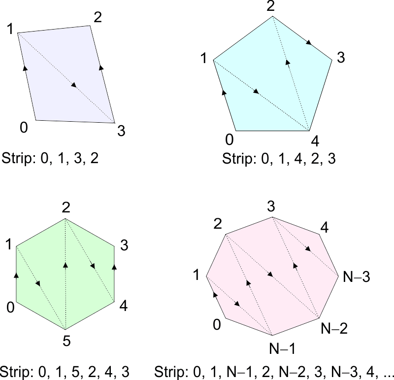
Triangle Tessellation |
| As the triangle is the simplest surface in 3D, a triangle strip can be used to create more complex surfaces. The figure below show how to create a quadrilateral, a pentagon, a hexagon, and the general case for any polygon (or a circle). The process of creating 3D surfaces using triangles is called triangle tesellation. Como el triángulo es la superficie más simple en 3D, una banda de triángulos puede usarse para crear superficies más complejas. La figura de abajo muestra cómo crear un cuadrilátero, un pentágono, un hexágono, y en forma general para cualquier polígono (y un círculo). El proceso de crear superficies en 3D usando triángulos es llamado teselación triangular. |
| Tip |
| In game development, artists use special software to create and edit 3D characters. Programmers, then, just load the characters into the program. The artist should try to use the smaller number of triangles while keeping a good appearance in the objects. Typically, the artist draws an image on each triangle to improve the quality of the objects. En el desarrollo de juegos, los artistas usan software especializado para crear y editar los caracteres 3D. Los programadores, entonces, sólo cargan los caracteres en el programa. El artista debe tratar de usar el menor número de triángulos mientras mantiene una buena apariencia en los objetos. Típicamente, el artista dibuja una imagen en cada triángulo para mejorar la calidad de los objetos. |
Game Platform |
| A game development platform may be a thin layer of encapsulation to help beginner programmer to create game using DirectX. Programmers, who have been working on game development for a long time, have their own set of classes for game development. Una plataforma de desarrollo de juegos puede ser una capa delgada de encapsulación para ayudar a los programadores novatos a crear un juego en DirectX. Los programadores que han estado trabajando en desarrollo de juegos por un largo tiempo, tienen su propio conjunto de clases para el desarrollo de juegos. |
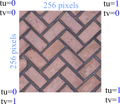
Texture |
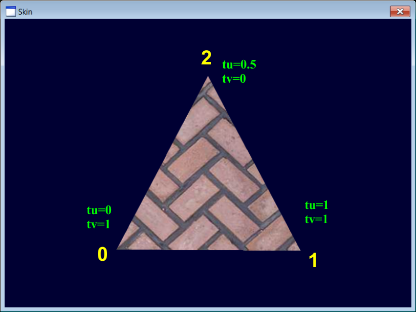
| A texture is an image that can be drawn on the surface of a 3D object. The texture size must be a power of 2: 16, 32, 64, 128, etc. The image for the texture can be loaded directly from a bitmap; the bitmap can be created from a resource or a file. The figure below shows how the values tu and tv are used to specify the corners of the image. These values are used when applying the texture. Una textura es una imagen que puede dibujarse sobre la superficie de un objeto en 3D. El tamaño de la textura debe ser una potencia de 2: 16, 32, 64, 128, etc. La imagen para la textura puede cargarse desde un bitmap; el bitmap puede ser creado desde un recurso o un archivo. La figura de abajo muestra cómo los valores de tu y tv son usados para especificar las esquinas de la imagen. Estos valores son usados al aplicar la textura. |
| Problem 2 |
| Create a DirectX application called Skin to draw a texture over a triangle. For this problem, you need an image of size 256x256. After creating the project, add a new class called TexTriangle to store the vertex and indexes of a triangle with texture. To display both sides of the triangle set the Cull Mode to D3D11_CULL_NONE. Add a DirectX object called Triangle and a DirectX scene called MainScene. For this problem, we will use a DX11::TextureVertexBuffer and a DX11::TextureShader. Cree una aplicación de DirectX llamada Skin para dibujar una textura sobre un triángulo. Para este problema, usted necesita una imagen de tamaño 256x256. Después de crear el proyecto, agregue una nueva clase llamada TexTriangle para almacenar los vértices y los índices de un triángulo con una textura. Para mostrar los dos lados del triángulo fije el modo de Cull en D3D11_CULL_NONE. Agregue un objeto de DirectX llamado Triangle y una escena de DirectX llamada MainScene. Para este problema usaremos un DX11::TextureVertexBuffer y un DX11::TextureShader. |
| Triangle.h |
| //____________________________________________________________ Triangle.h #pragma once class Triangle : public DX11::Object3D { public: float angleY = 0.0f; DX11::Texture texture; bool OnCreateScene(DX11::Engine& engine); . . . }; |
| Triangle.cpp |
| . . . void Triangle::OnUpdate(DX11::Engine& engine, float sec, float deltaSec) { angleY += (0.5f*deltaSec); world = DirectX::XMMatrixRotationY(angleY); if (angleY > DirectX::XM_2PI) angleY -= DirectX::XM_2PI; } void Triangle::OnRender3D(DX11::Engine& engine) // BE SURE TO USE A TEXTURE SHADER { engine.shaderTextu.Render(engine, world, vertexBuffer->GetIndexCount(), 0, 0, texture); } . . . |
| MainScene.h |
| //____________________________________________________________ MainScene.h #pragma once #include "Triangle.h" class MainScene : public DX11::Scene { public: Triangle triangle; void OnCreateScene(DX11::Engine& engine); . . . }; |
| MainScene.cpp |
| . . . void MainScene::OnCreateScene(DX11::Engine& engine) { //______________________________ 1. Set back color RGBA this->SetBackColor(0.0f, 0.0f, 0.0f, 1.0f); //______________________________ 2. Add children this->AddChild(triangle); this->AddChild(triangle.texture); //______________________________ 3. Camera & Light setup (light.ambientColor) . . . } . . . |
| Skin.h |
| #pragma once //______________________________________ Skin.h #include "Resource.h" #include "MainScene.h" class Skin : public DX11::Window { public: MainScene mainScene; DX11::TextureVertexBuffer vb; }; |
| Skin.cpp |
| . . . int APIENTRY wWinMain(. . .) { Skin app; app.engine.screenDevice.cullMode = D3D11_CULL_NONE; //_________________________________________________________ 1. Load texture const wchar_t* error = app.mainScene.triangle.texture.CreateData(L"floor.bmp"); if (error != nullptr) { ::MessageBox(NULL, error, L"floor.bmp", MB_OK | MB_ICONERROR); return 0; } app.engine.AddChild(app.mainScene.triangle.texture); //_________________________________________________________ 1. Vextex setup if (app.vb.CreateData(3, 3, D3D11_USAGE_DEFAULT, D3D_PRIMITIVE_TOPOLOGY_TRIANGLELIST) == false) { ::MessageBox(NULL, L"Unable to create vertex buffer", L"BasicX", MB_OK | MB_ICONERROR); return 0; } DX11::TextureVertex *vertex = app.vb.vertex; unsigned long *index = app.vb.index; //Bottom left vertex[0].position = DirectX::XMFLOAT3(-1.0f, -1.0f, 0.0f); vertex[0].texture = DirectX::XMFLOAT2(0.0f, 1.0f); //Top middle vertex[1].position = DirectX::XMFLOAT3(0.0f, 1.0f, 0.0f); vertex[1].texture = DirectX::XMFLOAT2(0.5f, 0.0f); //Bottom right vertex[2].position = DirectX::XMFLOAT3(1.0f, -1.0f, 0.0f); vertex[2].texture =DirectX::XMFLOAT2(1.0f, 1.0f); //Index setup index[0] = 0; // Bottom left. index[1] = 1; // Top middle. index[2] = 2; // Bottom right //_________________________________________________________ 2. Add vertex buffers to the engine app.engine.AddChild(app.vb); //_________________________________________________________ 3. Set vertex buffers to the 3D objects app.mainScene.triangle.vertexBuffer = &app.vb; //_________________________________________________________ 4. Scene setup app.engine.scene[L"mainScene"] = &app.mainScene; app.engine.SetCurrentScene(L"mainScene"); //_________________________________________________________ 5. Run the app return app.Run(. . .); } |
| Problem 3 |
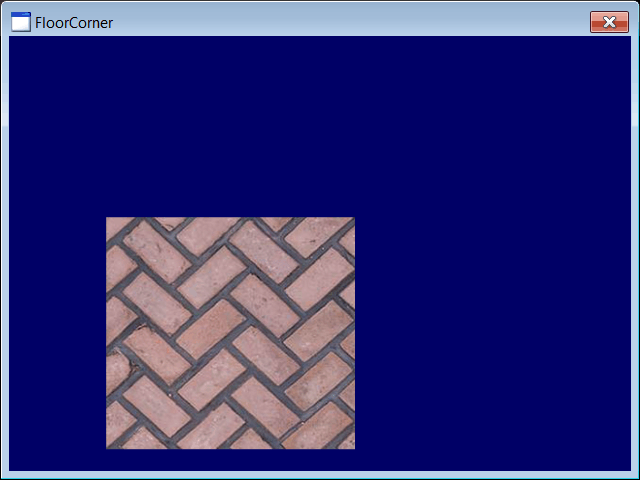
| Create a DirectX application called FloorCorner to draw an image in front of the 3D objects (2D drawing). For this problem, you need an image of size 256x256 . Add a DirectX scene called MainScene. Cree una aplicación de DirectX llamada FloorCorner para dibujar una imagen enfrente de los objetos 3D (dibujado en 2D). Para este problema, usted necesita una imagen de tamaño 256x256. Agregue una escena de DirectX llamada MainScene. |
| MainScene.h |
| //____________________________________________________________ MainScene.h #pragma once class MainScene : public DX11::Scene { public: DX11::TextureRect2D rect2D; void OnCreateScene(DX11::Engine& engine); . . . }; |
| MainScene.cpp |
| . . . void MainScene::OnCreateScene(DX11::Engine& engine) { //______________________________ 1. Set back color RGBA this->SetBackColor(0.0f, 0.0f, 0.4f, 1.0f); //______________________________ 2. Set position of rect2D rect2D.position.left = 100; rect2D.position.right = 356; rect2D.position.top = 200; rect2D.position.bottom = 456; //______________________________ 3. Add children children.AddChild(rect2D); //______________________________ 4. Camera & Light setup (light.ambientColor) . . . } . . . |
| FloorCorner.h |
| #pragma once //______________________________________ FloorCorner.h #include "Resource.h" #include "MainScene.h" class FloorCorner : public DX11::Window { public: MainScene mainScene; }; |
| FloorCorner.cpp |
| . . . int APIENTRY wWinMain(. . .) { FloorCorner app; //_________________________________________________________ 1. Load texture const wchar_t* error = app.mainScene.rect2D.texture.CreateData(L"floor.bmp"); if (error != nullptr) { ::MessageBox(NULL, error, L"floor.bmp", MB_OK | MB_ICONERROR); return 0; } app.engine.AddChild(app.mainScene.rect2D.texture); //_________________________________________________________ 2. Add vertex buffers to the engine app.engine.AddChild(app.mainScene.rect2D); //_________________________________________________________ 3. Set vertex buffers to the 3D objects //_________________________________________________________ 4. Scene setup app.engine.scene[L"mainScene"] = &app.mainScene; app.engine.SetCurrentScene(L"mainScene"); //_________________________________________________________ 3. Run the app return app.Run(. . .); } |
| Problem 4 |
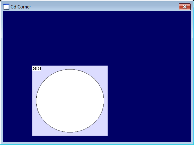
| Create a DirectX application called GdiCorner to draw an image in front of the 3D objects (2D drawing). Add a DirectX scene called MainScene. Cree una aplicación de DirectX llamada GdiCorner para dibujar una imagen enfrente de los objetos 3D (dibujado en 2D). Agregue una escena de DirectX llamada MainScene. |
| MainScene.h |
| //____________________________________________________________ MainScene.h #pragma once class MainScene : public DX11::Scene { public: DX11::TextureRect2D rect2D; void OnCreateScene(DX11::Engine& engine); . . . }; |
| MainScene.cpp |
| . . . void MainScene::OnCreateScene(DX11::Engine& engine) { //______________________________ 1. Set back color RGBA this->SetBackColor(0.0f, 0.0f, 0.4f, 1.0f); //______________________________ 2. Set position of rect2D rect2D.position.left = 100; rect2D.position.right = 356; rect2D.position.top = 200; rect2D.position.bottom = 456; //______________________________ 2. Add children this->AddChild(rect2D); //______________________________ 4. Camera & Light setup (light.ambientColor) . . . } . . . |
| GdiCorner.h |
| #pragma once //______________________________________ GdiCorner.h #include "Resource.h" #include "MainScene.h" class GdiCorner : public DX11::Window { public: MainScene mainScene; }; |
| GdiCorner.cpp |
| . . . int APIENTRY wWinMain(. . .) { GdiCorner app; //_________________________________________________________ 1. Create a bitmap CG::DDBitmap ddbitmap; const int width = 256; const int height = 256; ddbitmap.CreateCompatible(::GetDesktopWindow(), width, height); RECT rcPaint ={0, 0, width, height}; CG::Gdi gdi(ddbitmap, rcPaint, false); CG::Brush brush(RGB(220, 220, 255)); gdi.FillRect(0, 0, width, height, brush); const int radius = (int)(0.9*128+0.5); gdi.Circle(128, 128, radius); gdi.TextOut(0, 0, L"GDI"); //_________________________________________________________ 2. Create texture from bitmap app.mainScene.rect2D.texture.CreateData(ddbitmap); app.engine.AddChild(app.mainScene.rect2D.texture); //_________________________________________________________ 3. Add vertex buffers to the engine app.engine.AddChild(app.mainScene.rect2D); //_________________________________________________________ 4. Set vertex buffers to the 3D objects //_________________________________________________________ 5. Scene setup app.engine.scene[L"mainScene"] = &app.mainScene; app.engine.SetCurrentScene(L"mainScene"); //_________________________________________________________ 6. Run the app return app.Run(. . .); } |